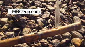
Water Leak from Hole in Copper Pipe (photograph)

Leak Rate Equations

Discussion
Leaks are common occurrences in pipes, tubes, and tanks. The leak rate is based on the pressure difference
between the inside and outside of the pipe, the crack or hole area, and specific gravity of the liquid.
The pipe leak rate calculator computes the leak rate of a liquid out of a circular or non-circular crack or hole in a pipe or tank.
The leak rate calculation has built-in specific gravity values for water, seawater, diesel fuel, SAE 30 oil, and gasoline.
Specific gravity can be entered for other liquids. If the leak rate is known, the calculator can compute
pressure or crack area (and diameter).
Equations and Derivation
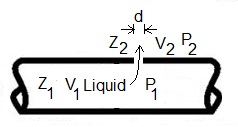
Liquid inside a pipe, tank, or other confined space flows out through a hole or crack.
The liquid in the pipe is at an elevation Z1, has pressure P1, and has velocity V1.
As the liquid exits the hole, it increases to velocity V2 through the hole, pressure P2 at the hole exit, and
an elevation Z2 of the hole exit.
Diagram of liquid flowing out of pipe through crack:

The Bernoulli equation (Munson et al., 1998, p. 114; bernoulli.php) describes flow of an inviscid fluid flowing from location 1 to location 2:

Specific gravity S = ρ/ρw,std, the ratio of density of the flowing liquid to density of water
at standard conditions (4oC), which is 1000 kg/m3.
The Bernoulli equation has many applications. Leak rate is one application where it is widely used. Since a pipe
is usually much larger diameter than the hole, V2>>V1. Since the elevation change Z2-Z1 is typically very small
compared to other terms in the Bernoulli equations for a pipe leak application, Z2-Z1=0. Thus:

Solve for V2:

Then with Q=V2A2, A=πd2 / 4, and ΔP=P1-P2:

Due to the viscosity of liquids and the tortuous path of the liquid through the hole, the measured leak rate from a hole is less that that computed by the above equation. To account for these effects, a discharge coefficient C is commonly used in the equation (e.g. Munson et al., 1998, p. 531; McAllister, 2005, p. 356):

C=0.61 is a typical value determined from experiments (McAllister, 2005, p. 356). Velocity out of the hole is computed approximately as:

A more accurate computation of velocity can be found using the methods at our Discharge from a Tank calculation which splits C into a velocity coefficient and a contraction coefficient. Our Bernoulli equation calculator applies the Bernoulli equation to many situations including pipe leak, but does not include a discharge coefficient.
Variables
The units shown for the variables are SI (International System of Units); however, the
equations above are valid for any consistent set of units. Our calculation allows a
variety of units; all unit conversions are accomplished internally.
A = Hole or crack area (m2).
C = Discharge coefficient. Need 0 < C ≤ 1. Suggested value is C=0.61 (McAllister, 2005, p. 356). For highly viscous liquids, C is lower.
d = Hole diameter (m).
g = Acceleration due to gravity, 9.8066 m/s2.
Q = Leak rate (m3/s).
S = Liquid specific gravity. In calculation, S for water is from Munson et al. (1998, p. B.2); seawater, SAE 30 oil, and gasoline are from Munson Table 1.6; and diesel is from Chevron (2007, p. 48).
V = Leak velocity (m/s).
ΔP = Pressure drop from inside of pipe to outside of pipe (or tank) (N/m2).
ρw,std = Mass density of water at standard conditions (4oC), 1000 kg/m3.
π = 3.1415926...
Error Messages given by calculation
"Need A > 0",
"Need 0 < C ≤ 1",
"Need d > 0",
"Need S > 0",
"Need Q > 0",
"Need ΔP > 0".
References
Chevron Corporation. 2007. Diesel Fuels Technical Review. Retrieved from
https://www.chevron.com/-/media/chevron/operations/documents/diesel-fuel-tech-review.pdf
McAllister, E. W. (editor). 2005. Pipeline Rules of Thumb Handbook. Elsevier - Gulf Professional Publishing.
Munson, B.R., Young, D.F, and Okiishi, T. H. 1998. Fundamentals of Fluid Mechanics. John Wiley and Sons, Inc. 3ed.
© 2017-2026 LMNO Engineering, Research, and Software, Ltd. All rights reserved.
LMNO Engineering, Research, and Software, Ltd.
7860 Angel Ridge Rd. Athens, Ohio 45701 USA Phone: (740) 707‑2614
LMNO@LMNOeng.com
https://www.LMNOeng.com
