
Units: cm=centimeter, ft=foot, gal=U.S. gallon, hr=hour, m=meter, MGD=million gallons (US) per day, min=minute, s=second
Topics: Equations Variables Error Messages References
Introduction
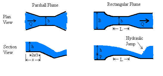
Flumes are used to measure flow rate (discharge) in open channels. They typically have widths from a few cm to 15 m or so. The water depth in the approach section of flumes typically can be between a few cm and about 2 m. Flumes, compared to weirs, have the advantage of less head loss through the device, yet are more complicated to construct and more difficult to analyze.
Head is measured in the flume upstream of the throat - in the so-called "approach channel". For Parshall flumes, head is measured upstream from the throat a distance of 2/3 of the length of the approach channel (x=length of approach channel in the above diagram). For the other three flumes, head is measured upstream from the throat a distance of 3 to 4 times the maximum expected head. This location is somewhat arbitrary because the head does not vary too much with position, so the exact location of the head measurement is not as important as for a Parshall flume. Since the rectangular, trapezoidal, and U flumes can have a raised throat (a hump), it is important to note that head is measured from the top of the hump rather than from the bottom of the approach channel.
This web page has calculations for four types of flumes - Parshall, rectangular, trapezoidal, and U shape. Each has advantages and disadvantages related to construction, installation, head measurement, sedimentation, and analysis. Parshall flumes are the most common. They were studied extensively in the mid 1900s. Their analysis is well documented in many texts. Their analytical maturity is exemplified by having both ASTM and ISO standards written for them (ASTM, 1991; ISO, 1992). Recently, Parshall flumes have gone out of favor due to their construction complexity and likelihood to trap sediment compared to newer flume designs.
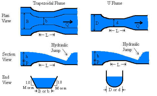
Rectangular and trapezoidal flumes function by having a constriction at the throat and/or a raised invert (bottom) at the throat. Either feature can cause critical flow at the throat in a properly operating flume. These flumes are simpler to construct, can be more easily fit into an existing channel, and can trap less sediment than a Parshall flume. However, the methodology relating discharge to measured head is more complex.
U-flumes (round bottom flumes), similar to Palmer-Bowlus flumes but with a semi-circular throat, are ideal for use in culverts or pipes. Critical flow is achieved by narrowing the throat or by raising the bottom of the flume at the throat. Analysis of U flumes is similar to that of the trapezoidal flume.
All flumes must be built with their dimensions in strict accordance with specifications in published documents such as the ISO and ASTM standards. Otherwise, discharge analysis must be conducted for the specific flume beginning with theory and proceeding to experimentation to modify the theory by physical observations.
Regarding analysis of flumes, flumes (like weirs) are designed to force a transition from sub-critical to super-critical flow. In the case of flumes, the transition is caused by designing flumes to have a narrowing at the throat, raising of the channel bottom, or both. Such a transition causes flow to pass through critical depth at the flume throat. At the critical depth, energy is minimized and there is a direct relationship between water depth and velocity (and flowrate). However, it is physically very difficult to measure critical depth in a flume because its exact location is difficult to determine and may vary with flowrate. Through mass conservation, the upstream depth is related to the critical depth. Therefore, flowrate can be determined by measuring the upstream depth, which is a highly reliable measurement.
The LMNO Engineering flume software is based on ASTM and ISO standards for flumes. These standards were developed from theoretical relationships and modified by experimental observations conducted over several decades. Our software is valid only for unsubmerged flows. An unsubmerged flow can be identified by the drop in water depth at the flume throat. In submerged flow, the downstream water backs up into the throat swallowing the drop making the drop difficult or impossible to identify. Analysis of submerged flow requires two head measurements - one in the approach channel and one in the throat.
Equations and Methodology
The methodology for the flume calculations follows that of ISO 9826 (1992) for the Parshall flume and ISO 4359 (1983, 1999) for the rectangular, trapezoidal, and U flumes. There are other sources of equations and methodology for flumes such as ASTM D 1941 (1991) for Parshall flumes and USBR (1997) for other flumes. Also, Herschy (1995) offers essentially a re-compendium of the ISO equations. Many other textbooks on open channel flow discuss flumes, but not in the degree of detail of the ISO or ASTM standards.
LMNO Engineering decided to follow the ISO methodology for the four flume types. ISO presents the methodology as a series of equations and graphs which have been agreed upon by an international panel after decades of research involving theory and experimentation. The ISO standards explain the validity and accuracy of their methodology. For Parshall flumes, the ASTM and ISO methods present similar, but not identical, methods. We have selected to follow the ISO method because it presents equations that are valid for a wider range of flume sizes.
Variable definitions can be found in the Variables section.
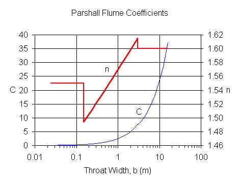
Parshall Flume (ISO 9826, 1992)
LMNO Engineering flume calculator allows 0 ≤ h ≤ 3 m and 0.01 ≤ b ≤ 16 m, but the
calculation is most accurate when used within the ISO 9826 recommendations of h ≤ 2
m and 0.152 ≤ b ≤ 15.24 m.
For b ≤ 0.152 m, C and n values are from Herschy (1995). For b > 0.152 m, C and n
values are from ISO 9826 (1992).
Q = C hn where Q is in m3/s and h is in m
Rectangular Flume
LMNO Engineering flume software allows 0 ≤ h ≤ 3 m, 0.01 ≤ b ≤ 16 m, b < B ≤ 104 m, 0 ≤ P ≤ 3 m, 0 < L ≤ 104 m, and F < 1. Note that if P = 0, then B must be > b. Likewise, if B = b, then P must be > 0. The calculator is most accurate when used within the ISO 4359 recommendations of h ≤ 2 m, 0.1 m ≤ b ≤ B, F ≤ 0.5, h/b ≤ 3, (bh)/[B(P+h)] ≤ 0.7, h/L ≤ 0.5, and h ≥ 0.05 or h ≥ 0.05 L (whichever is greater).
Order of computations (ISO 4359, 1983):
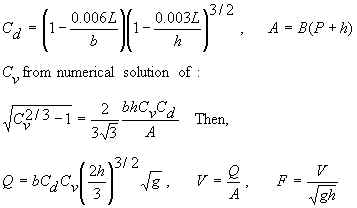
Cv can only be computed if hbCd/A<0.93.
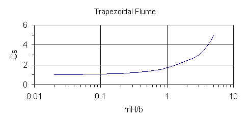
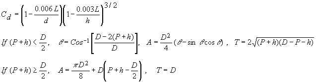
Trapezoidal Flume
LMNO Engineering calculator allows 0 ≤ h ≤ 3 m, 0.01 ≤ b ≤ 16 m, b < B ≤ 104 m, 0 ≤ P ≤ 3 m, 0 < L < 104 m, F < 1, and 0 < m ≤ 100, and 0 < M ≤ 100. The calculation is most accurate within the ISO 4359 recommendations of h ≤ 2 m, 0.1 m ≤ b < B, F ≤ 0.5, h/L ≤ 0.5, and h ≥ 0.05 or h ≥ 0.05 L (whichever is greater).
Order of computations (ISO 4359, 1983):
Let H=h and obtain Cs from the graph below. Note that the graph is only valid for 0.02 < mH/b < 5.
Then, Cv from numerical solution of:
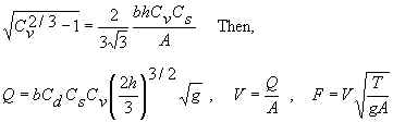
Cv can only be computed if hbCs/A < 0.93.
Since Cs and Cv are functions of both H and h, re-compute H = h Cv2/3, Cs, Cv, and Q. ISO 4359 suggests re-computing Q three times, but we re-compute Q until there are at least four significant digits of accuracy. Then, V and F are computed from the final Q.
U-Flume
LMNO Engineering calculation allows 0 ≤ h ≤ 3 m, 0.01 < b ≤ 16 m, d < D ≤ 104 m, 0 ≤ P ≤ 3 m, 0 < L ≤ 104 m, and F < 1. The calculation is most accurate within the ISO 4359 recommendations of h ≤ 2 m, 0.1 m ≤ d < D, F ≤ 0.5, h/L ≤ 0.5, and h ≥ 0.05 or h ≥ 0.05 L (whichever is greater).
Order of computations (ISO 4359, 1983):
Let H = h and obtain Cu from the graph below. Note that the graph is only valid for 0.1 < H/d < 3.
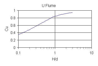
Then, Cv from numerical solution of:
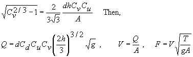
Cv can only be computed if hdCu/A < 0.93.
Since Cu and Cv are functions of both H and h, re-compute H=h Cv2/3, Cu, Cv, and Q. ISO 4359 suggests re-computing Q three times, but we re-compute Q until there are at least four significant digits of accuracy. Then, V and F are computed from the final Q.
Variables
Back to Calculation
ISO 4359 and ISO 9826 specify the indicated units for the equations shown above. Our
calculator allows you to specify a variety of units.
m = meters, s = seconds
A = Cross-sectional area of approach channel [m2].
b = Bottom width of flume throat [m].
B = Bottom width of approach channel [m].
C = Parshall flume constant [empirical units].
Cd = Coefficient of discharge for rectangular, trapezoidal, and U flumes
[unit-less].
Cs = Shape coefficient for trapezoidal flume [unit-less].
Cu = Shape coefficient for U flume [unit-less].
Cv = Coefficient of approach velocity for rectangular, trapezoidal, and U flumes
[unit-less].
d = Diameter of throat of U flume [m].
D = Diameter of approach channel of U flume [m].
F = Froude number of flow in approach channel [unit-less]. F < 1 is slow or
sub-critical flow. F > 1 is fast or super-critical flow.
g = Acceleration due to gravity, 9.8066 m/s2.
h = Measured head [m]. If there is a hump, then it is the vertical distance between
the top of the hump and the water surface.
H = Total head [m]. Measured head plus velocity head. H = h Cv2/3
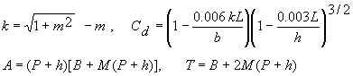
k = Constant used in trapezoidal flume computation [unit-less].
L = Length of flume throat [m].
m = Side slope of trapezoidal flume throat. Horizontal to vertical (H:V).
M = Side slope of trapezoidal flume approach channel. Horizontal to vertical (H:V).
n = Parshall flume power constant [unit-less].
P = Hump height [m].
Q = Flow rate through flume [m3/s].
T = Top width of approach channel [m].
V = Velocity in approach channel [m/s].
Error Messages
Back to Calculation
Input checks
If one of these
messages appear, the calculation and graphing is halted.
"Need h ≥ 0". Negative head was entered.
"Need h ≤ 3 m". Head cannot exceed 3 m.
"Need D, d > 0". For the U flume, upstream diameter or
throat diameter was entered as ≤ 0.
"Need D > d". For the U flume, upstream diameter must be
greater than throat diameter.
"Need b > 0". Parshall, rectangular, and trapezoidal
flumes Need throat width > 0.
"Need B > 0". Rectangular and trapezoidal flumes must
have approach width > 0.
"Need B > b". Trapezoidal flume must have approach width
greater than throat width.
"Need B ≥ b". Rectangular flume must have approach width
at least equal to throat width.
"Need 0.01 < b ≤ 16 m". Rectangular and trapezoidal flume
throat width must be in this range.
"Need B ≤ 10000 m". Rectangular and trapezoidal flume
approach width must be in this range.
"Need 0.01 ≤ d ≤ 16 m". U flume throat diameter must be in
this range.
"Need D ≤ 10000 m". U flume approach diameter must be in
this range.
"Need P > 0 if B = b". Rectangular flume must have P > 0 if
B = b or B > b if P = 0. Of course, it can have both P > 0 and B > b.
"Need P ≥ 0". Hump height cannot be negative (P does not
apply to Parshall flumes).
"Need P ≤ 3 m". Hump height cannot exceed 3 m (P does not
apply to Parshall flumes).
"Need L > 0". Throat length must be > 0 (L does not
apply to Parshall flumes).
"Need L ≤ 10000 m". This is an LMNO Engineering upper
limit. The ISO standards specify throat lengths for each flume type as a function of
expected flow rate. Rarely will a flume have a throat length longer than several
meters.
"Need 0< M,m ≤ 100". For the trapezoidal flume
approach channel side slopes (M) and throat side slopes (m) must both be between 0 and
100, measured as horizontal to vertical slope.
Input checks for graph
If one of these messages
appear, the graph will not proceed. Note that if h is out of range in the upper
portion of the calculation, a graph will not be shown.
"Min h must be ≥0". Minimum head entered for graph cannot be
< 0.
"Min must be < Max". Minimum head entered for graph must be
less than maximum head entered for graph.
"Min/Max must be < 0.99". Minimum head entered for graph must
be less than 0.99 times maximum head entered for graph. Otherwise, the minimum and maximum
heads are too close together to have good axis labels for the graph.
"Max h must be ≤ 3 m". Graph has maximum limit of h=3 m.
Run-time errors
The following messages may be
generated during execution and will halt execution:
The following messages are triggered by the head entered in the upper half of the
calculator. Its value, in conjunction with the other values entered, may cause Cd,
Cs, or Cu to be out of range. However, since the graph is
plotted for a range of heads, the graph may still be shown with the un-computable
flowrates plotted at Q=0.
"Cd will be <0", "Need (Cd)hb/A
< 0.93", "Need 0.02 < mH/b < 5", "Need (Cs)hb/A
< 0.93", "Need 0.1 < H/d < 3", "Need (Cu)hd/A
< 0.93". These variables or ratios are out of the acceptable ranges (see
Equations and Methodology above for further explanation).
"Infeasible input." May occur in numerical routine for computing
Cv if a combination of variables approaches machine precision. This
message very rarely, if ever, will occur since extreme values are screened out with the
input checks.
Run-time errors for graph
"Heads out of range for graph". All of the heads in the range entered for the
graph result in parameters (such as Cd, Cs, or Cu) that
are invalid, so no flow rates could be computed. Try lowering the minimum head
and/or increasing the maximum head.
"Some head calculations out of range of methodology, so Q shown as 0". Some heads in the range entered for
the graph result in parameters (such as Cd, Cs, or Cu)
that are invalid, so those could not be computed and were plotted at Q=0. Message appears on graph and table pages.
References
Back to Calculation
American Society for Testing and Materials (ASTM D 1941-91). 1991. Standard test method for open channel flow measurement of water with the Parshall flume. Available at http://www.astm.org.
Herschy, Reginald W. 1995. Streamflow Measurement. E & FN Spon (an imprint of Chapman and Hall). 2ed.
International Organization of Standards (ISO 4359). 1983. Liquid flow measurement in open channels - Rectangular, trapezoidal, and U-shaped flumes. Reference number: ISO 4359-1983(E).
International Organization of Standards (ISO 4359). 1999. Technical Corrigendum 1 for: Liquid flow measurement in open channels - Rectangular, trapezoidal, and U-shaped flumes. Reference number: ISO 4359:1983/Cor.1:1999(E).
International Organization of Standards (ISO 9826). 1992. Measurement of liquid flow in open channels - Parshall and SANIIRI flumes. Reference number: ISO 9826:1992(E).
ISO documents can be downloaded as .PDF files for a fee at http://webstore.ansi.org.
USBR. 1997. U.S. Department of the Interior, Bureau of Reclamation. Water Measurement Manual. 1997. 3ed. Available from http://www.usbr.gov/tsc/techreferences/mands/wmm/index.htm .
© 2001-2026 LMNO Engineering, Research, and Software, Ltd. All rights reserved.
LMNO Engineering, Research, and Software, Ltd.
7860 Angel Ridge Rd. Athens, Ohio 45701 USA Phone: (740) 707-2614
LMNO@LMNOeng.com
https://www.LMNOeng.com