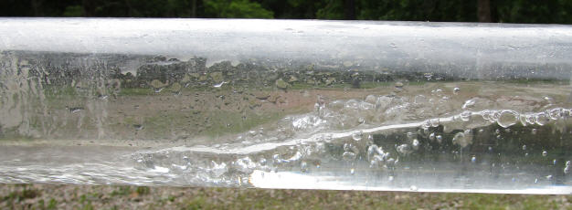
Hydraulic Jump in Sloped Water Pipe. Photograph of Steady Flow from left to right.
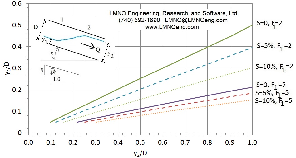
Graphical Solution for upstream or Sequent Depth to Diameter Ratio (y1/D, y2/D) as a function of Pipe Slope (S) and upstream Froude number (F1).
Topics: Equations Variables Error Messages References
Introduction
A hydraulic jump occurs in an open channel (or partially full closed conduit such as a pipe or culvert) where there is a transition from supercritical flow (F>1) to subcritical flow (F<1). A hydraulic jump can occur in any slope pipe - downward slope, horizontal, or adverse (upward slope). It may be especially of a concern if water (or other similar liquid) is flowing in a downward sloping pipe due to topography. The transition from a steep slope to a milder slope may result in a hydraulic jump. In a pipe, the transition to subcritical flow can cause the pipe to flow full. A full pipe can cause trapped air, especially if there are several hydraulic jumps in series, as pressure can build up between hydraulic jumps. Trapped pressurized air can cause unexpected high pipe pressures and potential pipe failure. Further, chaotic pounding of water on the pipe inside surface within the jump can impact pipe integrity. In design of a pipe if it is desired to avoid a pressurized flow situation, then computing the sequent depths of the hydraulic jumps is necessary to ensure pipes are designed to be large enough to avoid full flow.
To our knowledge (as of October 2018), there are no mathematical solutions for predicting the sequent (a.k.a. conjugate or downstream) depth of a hydraulic jump in a sloping circular conduit. In previous work, Montes (1998) indicates that hydraulic jump sequent depth has been determined mathematically in horizontal rectangular, trapezoidal, triangular, and parabolic open channels, as well as circular, horseshoe, inverted egg, and normal egg closed conduits. Lowe (2008, p. 2) mathematically determined the sequent depth for the additional horizontal shapes of elliptical and pipe arch culverts. Montes (1998) further indicates that the conjugate depth in hydraulic jumps in sloped rectangular channels has been determined analytically.
LMNO Engineering's work on sloping circular pipes was presented by Ken Edwards at the National Hydraulic Engineering Conference (NHEC, 2018). Our analysis shows that, for a given upstream Froude number, the conjugate depth is greater in a sloped pipe than in a horizontal pipe. Since Froude number is proportional to flow rate, the conjugate depth is likely to be greater in a sloped pipe than in a horizontal pipe for a given flow rate. Thus, for a sloped circular pipe, it is important to use an analysis that considers the pipe slope rather than simply using a horizontal pipe sequent depth chart which was all that had been previously available. Using the figure above as an example, if F1 is 2, S is 10%, and y1/D is 0.3, then y2/D=1.0. However, if the horizontal computation for sequent depth is used, then y2/D is 0.6 which would lead one to erroneously believe the pipe would not flow full.
EquationsBack to Calculation
Drawing of a side view of a hydraulic jump in a sloped pipe:
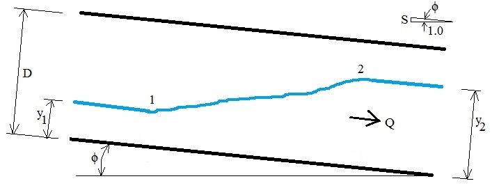
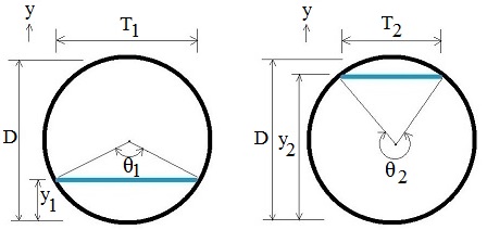
Drawings of upstream and downstream pipe flow areas and top widths (y coordinate is perpendicular to pipe wall; y is vertical if pipe is horizontal):
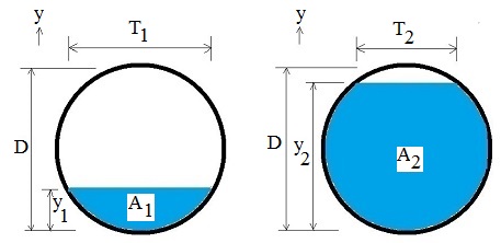
Drawings of upstream and downstream central angles:
Geometry equations at any cross-section and equations for slope and Froude number (Chaudhry, 2008, p. 10):

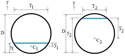
Drawings of upstream and downstream centroids of flow areas C1, C2 and distances from water surface to the centroids y1, y2:
Control volume showing forces and momentum in and out of control volume (Lowe, 2008, p. 7; similar to Chow, 1959, p. 426):

The general momentum equation in the x-direction is similar to Chaudhry (2008, p. 44) and Lowe (2008, p. 7) for a sloped channel. Friction is commonly assumed to be negligible compared to other terms in the equation (Chaudhry, 2008, p. 44):
![]()
Fy1 and Fy2 are assumed to be hydrostatic:
![]()
A unique aspect of the analysis of hydraulic jump in a sloped pipe is inclusion of the weight term. For a horizontal pipe, there is no component of the weight in the flowing direction (since sinΦ=0) which makes the horizontal analysis much simpler. For a sloped pipe, the component of weight in the direction of flow is:
![]()
The control volume approximates the jump as having a trapezoidal shape with y varying linearly with x. With mathematical substitutions for central angle θ, integration from θ1 to θ2, and substituting expressions involving the centroid of the areas, the hydraulic jump volume is:
![]()
Hydraulic jump length cannot be determined from first principles. Experiments are required (French, 1985, p. 89). Franzini & Finnemore (1997, p. 479) indicate that jump length is typically 4y2 to 6y2. There are many equations for hydraulic jump length for horizontal channels but not for sloped conduits. Since any formula selected would be an estimate, LMNO Engineering has selected a simple equation from Montes (1998, p. 335):
L = 4.5 y2
After substitutions and algebra, the hydraulic jump in a pipe equation is:
![]()
The above hydraulic jump equation can be solved analytically for Q. LMNO Engineering solves the equation numerically for y2 in the calculation at the top of this page. For S=0, it reduces to Lowe (2008, p. 114) and Montes (1998, p. 337). The hydraulic jump equation does not include any additional water level rise due to air entrainment. Due to the choice of hydraulic jump length of L=4.5y2, the above equation is only valid if channel slope ≤ 22.22%.
Variables
Back to Calculation
Units shown in SI for use in equations: kg=kilogram, m=meter, N=Newton, s=second.
Calculation allows a variety of units (most are defined in the calculation above but these are not): cm=centimeter, ft=foot, m=meter, min=minute, s=second.
A = Flow area (m2).
C = Location of centroid of flow area.
D = Culvert or pipe inside diameter (m).
f = Friction force (N).
F = Froude number.
g = Gravitational acceleration = 9.8066 m/s2.
L = Control volume length (m).
Q = Flow rate (discharge) (m3/s).
S = Pipe slope. Vertical to horizontal ratio (m/m). Decimal (not percent) in equations but enter as percent in calculator. % slope = 100 x decimal slope.
T = Top width (m).
u = Horizontal coordinate direction.
V = Average velocity (m/s).
∀ = Volume of control volume (m3).
x = Coordinate direction in direction of flow.
W = Weight of water in control volume (N).
y = Water depth (m) or coordinate direction (perpendicular to flow).
y = Depth to centroid (m).
z = Vertical coordinate direction. Also elevation of water surface (m).
Φ = Slope angle (radians).
θ = Central angle (radians).
ρ = Mass density of water (kg/m3). Since ρ is in every term of the momentum equation, it drops out. Thus, the sequent depth is independent of density. However, the solution is not valid for highly viscous liquids since the friction term f is neglected.
Subscript 1 is upstream, 2 is sequent (conjugate, downstream)
Error Messages
Back to Calculation
Initial checks: "Need Q > 0", "Need S ≥ 0", "Need S ≤ 22.22%", "Need D >0",
"Need y1 > 0", "Need y1 < D", "No jump - F1 is ≤1".
Run-time messages:
"No jump. F2 will be ≥1".
"Warning: full pipe".
"No jump. Need larger Q or smaller y1".
"No jump. Need smaller Q or larger y1".
References
Back to Calculation
Chaudhry, M. H. (2008). Open Channel Flow. 2ed. Prentice-Hall, Inc.
Chow, V. T. (1959). Open Channel Hydraulics. McGraw-Hill, Inc.
Edwards, K. B., Edwards, D. J., and McKenzie, S. A. (2018). Computation of Hydraulic Jump's Sequent Depth in Sloped Circular Water Pipe. 2018 National Hydraulic Engineering Conference. Advancing Hydraulic Engineering through Innovation and Resilient Design. Columbus, Ohio. August 29, 2018. Video of presentation can be viewed at
https://www.youtube.com/watch?v=0k6RJyqSA1I
Franzini, J. B. and Finnemore, E. J. (1997). Fluid Mechanics with Engineering Applications. 9ed. McGraw-Hill.
French, R. H. (1985). Open-Channel Hydraulics. McGraw-Hill, Inc.
Lowe, N. J. (2008). Theoretical Determination of Subcritical Sequent Depths for Complete and Incomplete Hydraulic Jumps in Closed Conduits of Any Shape. Brigham Young University Scholars Archive. Master of Science thesis. Retrieved from
https://scholarsarchive.byu.edu/cgi/viewcontent.cgi?referer=https://www.google.com/&httpsredir=1&article=2618&context=etd
Montes, S. (1998). Hydraulics of Open Channel Flow. ASCE Press.
© 2018-2026 LMNO Engineering, Research, and Software, Ltd. All rights reserved.
LMNO Engineering, Research, and Software, Ltd.
7860 Angel Ridge Rd. Athens, Ohio 45701 USA Phone: (740) 707‑2614
LMNO@LMNOeng.com
https://www.LMNOeng.com
