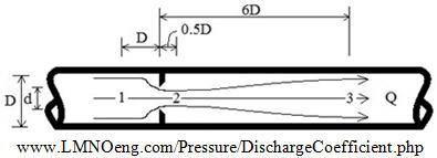
Discharge Coefficient Diagram and Conceptual Flow Lines for an Orifice in a Pipe

Discharge Coefficient Equation

Valid for 0.4 ≤ C ≤ 0.8 and 0.2 ≤ β ≤ 0.7
Derivation of Discharge Coefficient Equation
Steady flow of an incompressible fluid through an orifice based on a discharge coefficient:

Pressure loss from location 1 to 3 in the pipe written in terms of discharge coefficient:

Pressure loss from 1 to 3 in the pipe due to the orifice written in terms of minor loss coefficient:
![]()
Also:
![]()
![]()
The goal is to solve the above equations for K. Begin by equating discharge coefficient equation (2) to (3):


Solve for K in terms of discharge coefficient:

Many pipe flow analysis programs do not readily implement orifice discharge coefficients because they use K's instead. Hence, having a value for K based on the orifice discharge coefficient is useful for flow calculators.
Symbols and units for discharge coefficient equations: Ao=orifice area (m2), Ap=pipe area (m2), d=orifice diameter (m), D=pipe inside diameter (m), P1-P2=differential pressure (N/m2), P1-P3=non-recoverable pressure difference (N/m2), Q=flow rate (m3/s), Vo=velocity through orifice (m/s), Vp=velocity in pipe (m/s), ρ=fluid mass density (kg/m3).
Reference: LMNO Engineering - Large diameter orifice flow meter calculation for liquids
© 2017-2025 LMNO Engineering, Research, and Software, Ltd. All rights reserved.
LMNO Engineering, Research, and Software, Ltd.
7860 Angel Ridge Rd. Athens, Ohio 45701 USA Phone: (740) 707-2614
LMNO@LMNOeng.com https://www.LMNOeng.com
